Contents and links:
- Main article as published in Machinery, July 2016
- The complete range of WFL processes
- How being bigger makes some things easier
- WFL investments to underpin the M200’s production
- More images of the machine and various machining operations
Austria’s WFL Millturn Technologies threw open the doors of its Linz headquarters site in June to a select group of some 200 visitors who had one thing in common – the desire to efficiently machine the very largest of workpieces in the minimum of operations, on a single machining platform. One-hit, or at least single-platform, machining is what WFL is all about with its ‘Millturn’ range of horizontal spindle CNC lathes, so doing it a bit larger is just more of the same, right? Well, no.
The new top-of-the-range M200, available in the UK from Kyal Machine Tools (01780 765965), has a maximum turning diameter of 2 m and can carry a part weighing up to 60 tonnes and measuring 14 m in length between centres. Its next-in-line ‘smaller’ brother, the M150, claims figures of 1,560 mm, 20 tonne and 8 m (in fact, at 8 m centre distance, turning diameter is reduced to a ‘mere’ 1,440 mm).
The new model can employ all the same WFL technologies and processes (see online article) as do all the others, while it can deliver comparable accuracy to that achieved by the M150. But that WFL is able to deliver those same outputs at this size is the real story.
On show during the early June event was the machine that will be the first to be installed; although it won’t actually be delivered for another 18 months or so. Explains Martin Kaukal, director sales/vice president: “This was a condition of the order. We need time to prove out the processes that we offer on this machine.”
 The demonstration component for the event measured 1,670 by 3,090 mm (dia by length) and weighed 24 tonne. Machining elements include: crank pin milling; web milling; profile milling; dovetail; profile milling, fir tree; B-axis turning; deep hole drilling with ejector drill (seat pocket); CNC special contour boring bar; radial milling and boring; ring groove turning; OD turning with boring bar, long overhang; 5-axis miling; radial drilling and boring gear cutting
MIDDLE-SIZE EXAMPLE
The machine on view was the middle-size 100 kW main spindle, 6.5 m bed length unit (see below for more range specifications). It also features for this customer: 180 tools in a chain-type magazine, HSK125 interface; deep hole boring tool magazine and separate boring bar head for 2.2 m bars; U-axis, used with facing heads, seat pocket machining tools and ID tools; 300 mm diameter tailstock quill; 80 bar coolant; and CrashGuard software.
Over the next five years, orders for 15 M200s are anticipated – the company produces 70-100 machines annually, assembling a maximum of six machines at any one time.
If this first delivery seems a long one, the journey to actually deciding to make the new model has been far more lengthy, as Kaukal reveals: “The first ideas for such a machine go back 15 years. And before we embarked on the design, there was a period of about three years where we checked our suppliers’ capabilities. In particular, telescopic covers nearly 3 m high and many metres long were a critical issue. [The company assembles only, although has in-house machining capability to support modifications and so on.]
“It was not an easy decision for us to build such a machine. But because of the demand, and especially because of our long-term customers and our experience over several years where we couldn’t offer the right machine size, we decided to close this gap.” And closing that gap has effort has expended sustained effort.
“It required much capacity in R&D to develop such a machine, and you have to balance it with other demands. It didn’t take all of our capacity, but did take a significant proportion for several years; roughly three years, in fact. Within that period, we had a prototype machine arrangement for one of those years, which was operated by the R&D department in the workshop. It comprised a bed, some slideways and several key components where we tested under load for one year the performance of critical systems, so there has already been a long testing period before we built the first machine.”
This length of development is certainly not the norm, but the size of the machine is key in this. Kaukal again: “When we talk about a workpiece weight of 60 tonnes and you are holding this between centres, you can imagine the force on the tailstock and the heat created in the headstock bearings; you have to manage all these challenges.
“We have also increased the turning diameter from 1.5 m to 2 m. Now, that doesn’t sound that dramatic; however, the influence on the design was the huge increase required in axis travels. So, the determining factors for the size of the machine were the required X- and Y-axis strokes, and here we are talking about 100% increase, compared to the M150. That means we have an X-axis stroke of 2.2 m and Y-axis travel of 1.4 m.” And this meant that simply scaling up its 60° slantbed design was not possible, because it would have created “a monster”.
TRAVELLING-COLUMN DESIGN
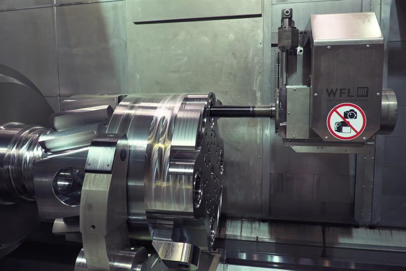
So the M200 employs a travelling-column/ram approach, with the column sitting behind those near-3 m high telescopic covers and moving in the Z-axis. The ram protrudes through the covers into the work area and moves in X1 (vertical) and Y axes (horizontal) – no pictures of this arrangement were allowed, however. The B-axis and the single static or driven tool spindle are located on the end of this ram (see below).
The column also carries the separate boring bar head (see below), which moves on column-mounted X2-axis rails. On the smaller 60° slantbed models, a separate slideway system carries the boring head.
But during both assembly and operation, the advantages of the existing 60° slantbed concept used on the smaller machines were proven true, because it was much more challenging to deliver the same results as regards precision, explains Kaukal, adding that, nevertheless, the M200 is equal to the M120 and M150 models in this regard.
A hugely important design element is the model’s cast iron bed. The sales director again: “One of the key ideas was to build a machine that has so much stiffness that the foundation has no influence on [machine] geometry, as is usually the case. The foundation is only responsible for carrying the load and so requirements for it [the foundation] are relatively low.”
For machines up to a bed length of 8 m, a single casting is employed. All bed castings are supplied by Germany’s MAN, a company well used to producing engine blocks for ships’ diesel engines. For this machine, however, SG cast iron is employed, as is the case for modern light and strong car engine crankshafts – SG cast iron has a higher tensile strength but maintains good dampening qualities, allowing a lighter casting than would otherwise be possible.
He continues: “We wanted to keep the bed as long as possible in one piece, but there is a weight limitation for road transport, about 80 tonnes, so the bed has a lot of ribs but they have a large variation in thickness.” Smaller machines have a more traditional design with fewer but thicker ribs, as they easily meet the 80 tonne limit.
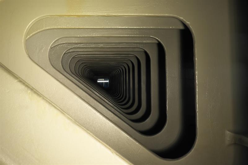 Looking through the 8 m bed; many ribs of variable thickness are employed
Finite element analysis (FEA) to precisely position ribbing was employed, with the final design a secret WFL is not willing to share via publicised images. Each rib has its own shape, Kaukal reveals, describing it as: “Kind of bionic designing, like a tree; where the forces are strong, you have more material, where they are weaker, you have less, to optimise the relationship between weight and stiffness.” What FEA does not reveal is vibration behaviour, however, and it is here that WFL’s experience, its knowledge of requirements, and testing combine to deliver the optimal combination of stiffness, vibration and weight for the M200. As for beds longer than 8 m, there’s a two-piece approach employing an in-house developed novel joining approach that maintains bed integrity and performance.
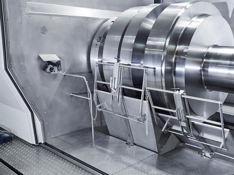 A novel hinged platform allows for good operator access to the M200's working envelope
All this design detail is fundamental, but the customer wants performance and capability. In responding to how WFL will distinguish itself in the market with customers versus other suppliers of machines of this type, the response is: “Those who know WFL know they can look into any detail and, although the design takes a little longer, everything is 100% considered and accurate.
“Also, we have a complete system. It is modular and can meet the requirements of all of our target industries, and those requirements are completely different. For a large crankshaft you might need a machine with 14 m centre distance and five steady-rests, each with a huge opening diameter; for other projects the challenge may be a workholding solution for 60 tonnes; in other cases boring holes to a depth of 3 m might be the need. No other company has this breadth of uncompromised solutions. Other traditional suppliers of such large machines are using attachments for deep hole boring that are very inconvenient, for example. So, while it may have been possible to do all these operations [on other machines], the way they were done was not so smart.
“It is very difficult to design a machine that can fulfil the maximum of all these operations but which still must be easy to use and be offered at a competitive price.” That price starts at €4.5 million and goes up to, say, €10 million; lead time is typically 18 months. Your order will arrive in some 14 lorries and take up to a month to install and commission. And, yes, the development of an even larger machine has already been requested and, based on the new design, this is possible but not immediately planned.
Seemingly confirming WFL’s breadth of capability claim, the machine on show at the June event is going to a Brazil-based subcontractor that supplies a major aerospace OEM in that country but which will also service markets outside of this, including oil and gas, and power generation (large shafts).
As for the UK, Simon Pollard, managing director of Kyal Machine Tools, sees much potential: “We see quite a few customers – new customers – who are genuinely interested. There are parts that are being made in multiple operations on multiple machines – vertical lathes and horizontal borers – that, if they were made on this [M200], could be completed on a single machine, reducing cost and lead times, while improving component precision and quality.”
Specification at a glance
Model variations
[] Component weight – (three models) 20, 35, 60 tonnes
[] Main spindle (kW, 100% duty cycle; speed, rpm; torque, kNm) –
(three models) 100/1,000/9.8; 120/500/40; 160/350/80
Common across all models
[] Standard capacity (diameter by length) – 2 m by from 5 to 14 m
[] Milling spindle unit – 80 kW, 3,500 rpm, 1,800 Nm
[] Turning boring milling unit B-axis range - 220° (±110°)
[] Tool interface, length and tool weight – HSK125, 1,000 mm, 40 kg
[] Tool magazine capacity – 30, 60 or 90 in a disc system; 200 in a chain system
[] Long boring bar magazine, capacities – 3 m length, 300 kg weight and up to 15 bars
(for use with separate, column-mounted boring unit)
[] Integrated Y-axis – 1,400 mm (-800/+600)
[] Separate slide with Y-axis supports disc milling cutters of up to 1 m diameter,
for stator groove milling, for example
[] Coolant pressure – 80 bar as standard; up to 350 bar optionally
[] Centre quill diameters – 300/500 mm
Main article ends
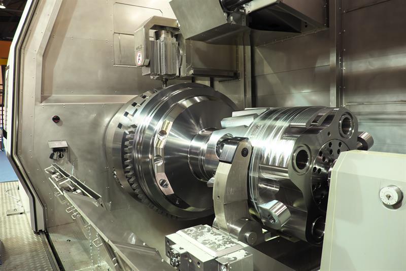
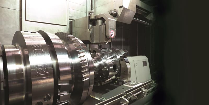
Above: The demonstration component, looking towards the headstock
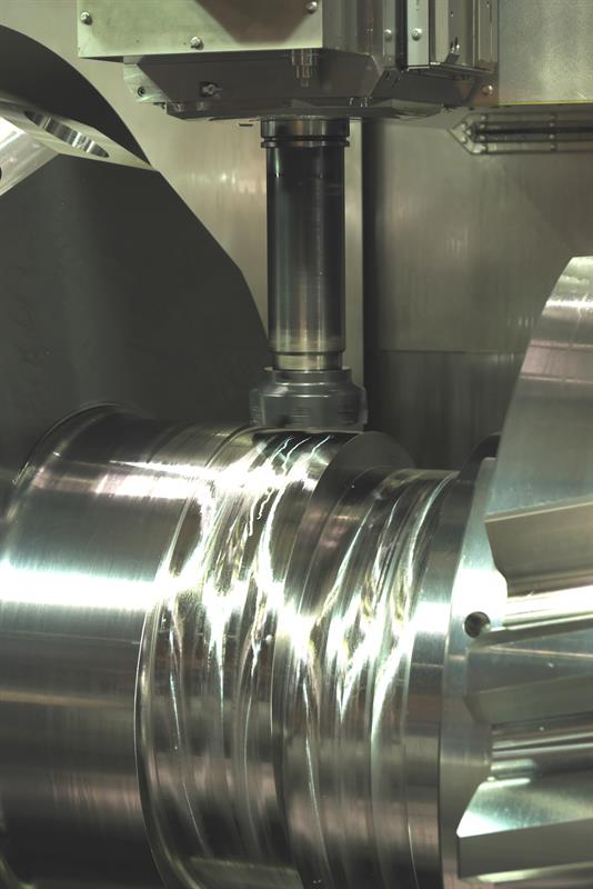
Above: Machining the crankshaft detail on the demonstration part
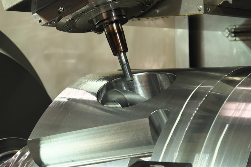
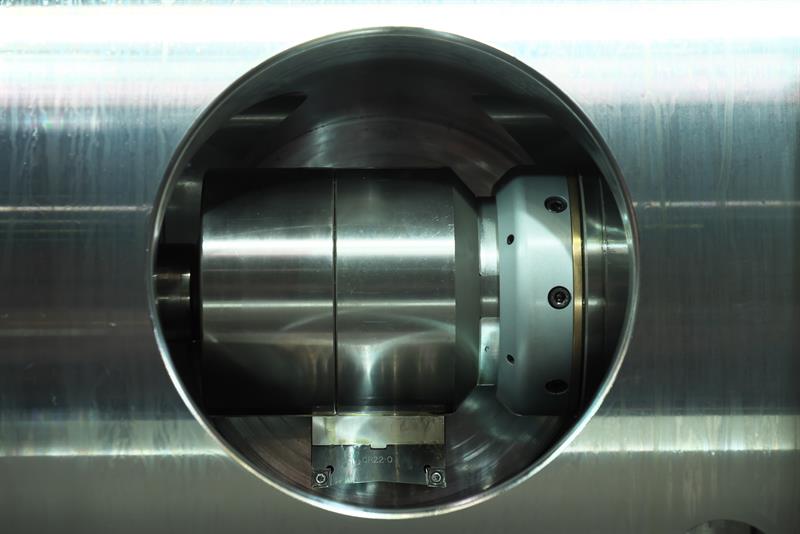
Above: The B-axis head machining a chamfer in a bore
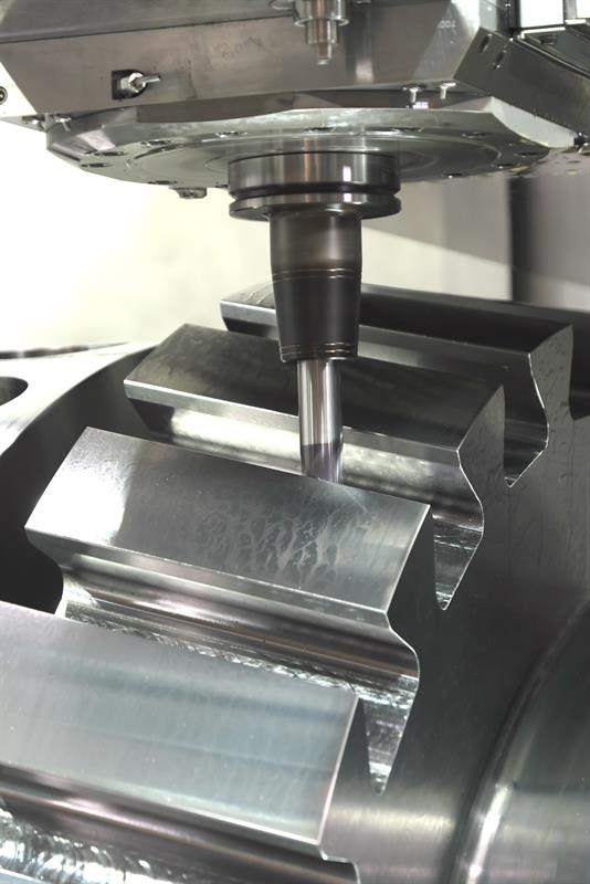
Above: Machining a blade root detail
Above: Machining a bore using the B-axis spindle in this case, not the separate boring bar head
Above: Seat pocket machining, which employs the M200's U-axis to expand the cutting edges into the bore
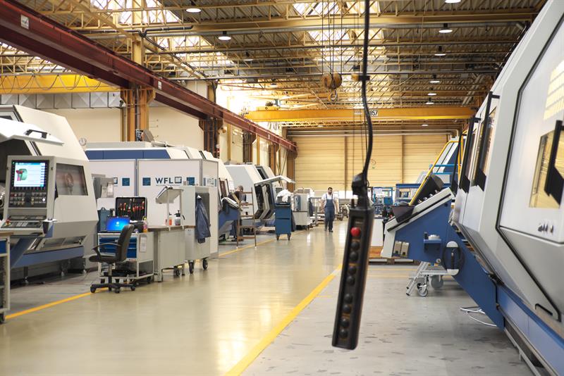
Above: Inside WFL's assembly hall for smaller machines
WFL technologies and processes
•Turning - http://www.wfl.at/Technology/Turning?sc_lang=en
•Boring (including deep hole drilling) - http://www.wfl.at/Technology/Drilling?sc_lang=en
•In-process measurement - http://www.wfl.at/Technology/InProcessMeasuring?sc...
•Circular milling - http://www.wfl.at/Technology/CircularMilling?sc_la...
•Turn-milling (turning with a rotating milling cutter) - http://www.wfl.at/Technology/Turnmilling?sc_lang=e...
•B-axis turning - http://www.wfl.at/Technology/BAxisTurning?sc_lang=...
•Shaping - http://www.wfl.at/Technology/Shaping?sc_lang=en
•Five-axis milling - http://www.wfl.at/Technology/5AxisMilling?sc_lang=...
•Grinding and fine machining - http://www.wfl.at/Technology/GrindingAndFineMachin...
•ID machining (including bottle boring and seat facing) - http://www.wfl.at/Technology/IDMachining?sc_lang=e...
•Gear hobbing - http://www.wfl.at/Technology/GearHobbing?sc_lang=e...
•Cam milling - http://www.wfl.at/Technology/CamMilling?sc_lang=en
•Pin milling - http://www.wfl.at/Technology/PinMilling?sc_lang=en
•Special tool heads - http://www.wfl.at/Technology/HighSpeedToolsAndAngl...
•Additive manufacturing – See http://www.machinery.co.uk/machinery-features/wfl-...
The additive manufacturing capability makes use of a dioed laser unit of unit up to 10 kW power mounted in the turning-boring-milling. This head also features coaxial powder supply. The head and media supply can be automatically loaded/unloaded. A wide material spectrum is available.
Use include: building of wear-, heat- and corrosion-resistant layers; repair of wear areas.
Advantages: high build-up rate; minimum distortion; highest utilisation of powder; and user-defined layer thickness
Advantages of size
Not everything is made more difficult in such a large machine. The ability to incorporate a much larger disc cutter, up to 1 m, for rotor slot milling is realised, allowing “an uncompromised” solution. It is easier and less costly to integrate both this capability and deep hole boring, as the relevant units can each be located on the travelling column of the M200, whereas separate units are required otherwise. Also, with a larger working envelope, it is easier foroperators to clearly see, as machine parts are not so crowded, while machine movements are slower than for a smaller machine, effectively making operation easier and safer. And while some 14 lorries might be required to deliver an M200, for smaller machines the lorries may be fewer but a larger lorry size is required – an M120 or M150 is broken into just three parts, for example.
Big investments
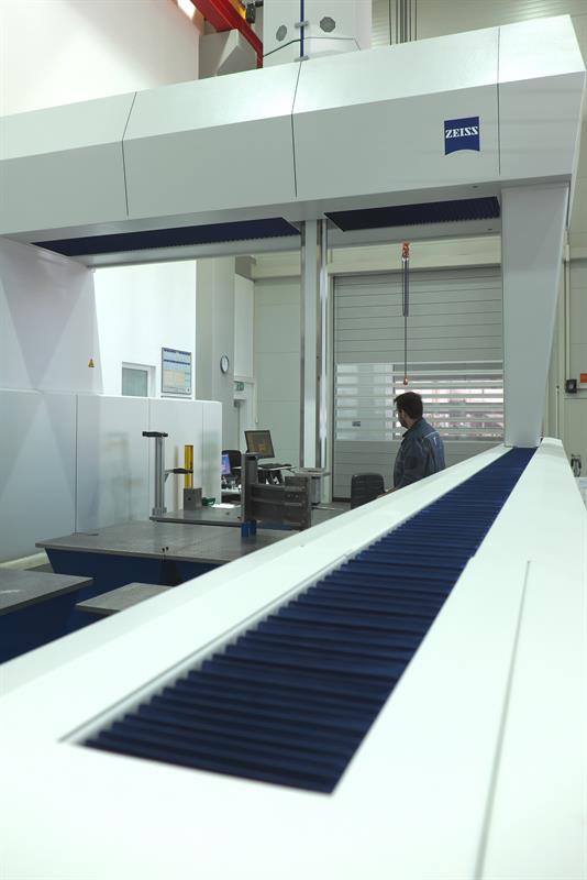
Although investment by WFL in machinery to manufacture the M200 has not been necessary, two critical investment have been made: a Zeiss MMZ G 30 60 20 co-ordinate measuring machine (Hexagon Manufacturing Intelligence, 01952 681300) and upgraded overhead crane capacity, from 16 tonne to 32 tonne. The CMM is housed in a new, separate building within the WFL site, and its capacity of 3 by 6 by 2 m means that the company has the largest such inspection capability in Austria. Required to measure both incoming machined M200 parts and the components it produces, the CMM’s stated accuracy is MPEE = ±(3.2+L/400 mm), while it can manage objects weighing 70 tonne.
Below, the largest CMM in Austria is now housed at WFL's Linz plant