
While there is a continual linear advance of technology in the areas of machine tools and cutting tools – the former performing ever more efficiently and accurately at increasing spindle speeds and axis feed rates, and the latter supporting those more demanding cutting conditions while delivering ever better cutting edge stability and durability in increasingly challenging materials – new machining/cutting techniques pop up more infrequently and in more ad hoc fashion.
Last year was a good year for them, though, with Emuge-Franken/Siemens’ ‘punch-tapping’ solution gathering momentum; Sandvik Coromant’s Prime Turning innovation, supported by Mastercam CADCAM, unveiled in the first quarter; a September EMO exhibition world premier by German tooling firm Vandurit, supported by Open Mind CADCAM software; plus advances in barrel cutter design and application demonstrated by WNT (part of the Ceratizit Group) and supported by, again, Open Mind CADCAM software and underlined at an event in October 2017. The common theme was new insert/cutter designs combined with novel CADCAM or CNC machining cycles. Slightly away from this pattern, in December Machinery came across Sandvik Coromant’s Y-axis parting-off strategy that exploits new tooling and CNC lathes having Y-axis.
Ahead of these latest developments, we have seen CADCAM cutting strategies developed in isolation, such as trochoidal milling (‘Trochoidal milling, a refresher’, below) – although that was followed by cutters able to better exploit the technique – and then constant radial tool engagement or constant chip thickness/load milling techniques, such as are employed in Vero Software’s Waveform, Solidcam’s iMachining, Autodesk Powermill’s Vortex and Open Mind’s MAXX Machining roughing module (which uses Celeritive Technologies’ VoluMill – available standalone, too). Differences are claimed, but smoother machining with constant cutter/spindle loads are central. For turning, in 2016, DP Technologies presented ‘ProfitTurning’ in its Esprit CADCAM system (see ‘Esprit ProfitTurning’, below). Constant chip load, however, is the theme again here.
On the whole, the development of these techniques has been driven by the need to cope with the machining of more challenging materials. So, let’s take a look at these innovations, the four tool/CADCAM or CNC strategy combinations and the one tool/machine tool capability combo.
PUNCHING PRETTY
In January 2017, Machinery reported (https://is.gd/ejaruv) on a tapping process breakthrough. Emuge-Franken and Siemens had worked with car maker Audi in Germany to develop tools and a process, both patented, that reduces M6 threaded hole production time by up to 75% – punch-tapping. Special tap designs are supported by Siemens 840D sl and 828D controls having the relevant cycle. Suggested for series production of aluminium alloy and comparable light material parts, the punch-tap process is suitable for both blind and through holes. Under development and in use for a few years, in fact, it was originally only available to automotive companies, but as of January this year, the process is available for use by any manufacturing sector, with thread sizes M4, M5, M7 and M8 now available, as well as custom solutions.
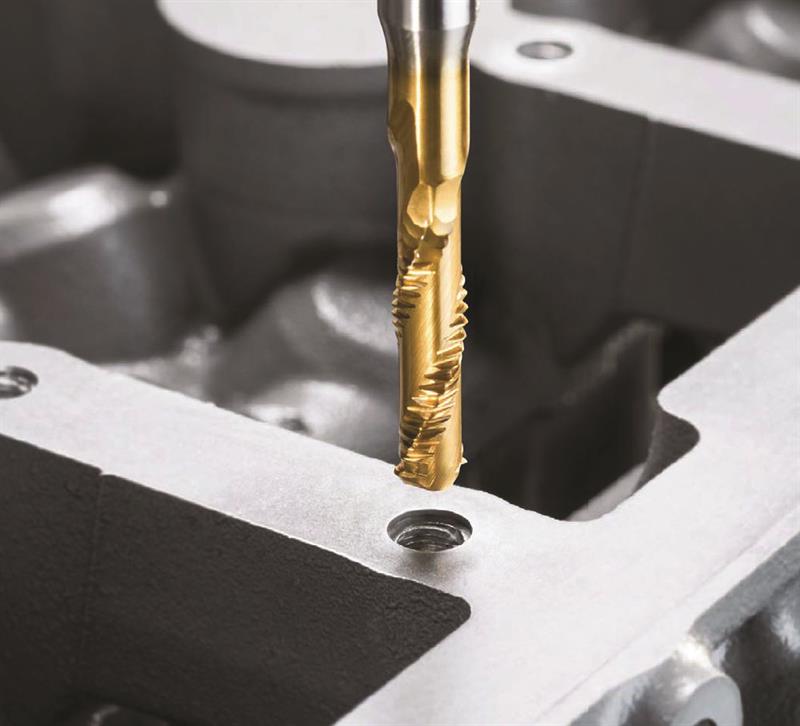 Emuge-Franken and Siemens have developed punch tapping
Sandvik Coromant’s PrimeTurning sees the cutting tool enter the component at the chuck end and remove material as it travels towards the ‘front’ of the component. Using specially designed inserts and toolholders, a small entry angle is achieved that promotes increased feed rates and significant productivity gains, typically around 50%.
The basic technique itself is not new, but the problem has always been chip control, with long, curved chips forcing manufacturers to apply angles of around 90° to reach the shoulder. With a 25-30° entry angle, chip control issues are dissipated, with the small entry angle and higher lead angle creating thinner, wider chips that spread the load and heat away from the nose radius, resulting in increased cutting data and/or tool life.
All-directional turning can be performed using the same tools as the inserts have three edges/corners, one for longitudinal turning, one for facing and one for profiling. Parts made from ISO P (steel), M (stainless steel), K (cast iron) and S (heat-resistant super-alloys and titanium) materials can benefit. In fact, almost any general turning operation will achieve gains, with returns said to be impressive for high volume batch sizes (>100-off), or when machining large components where there is a need to reduce set-up time, production interruption and tool changes.
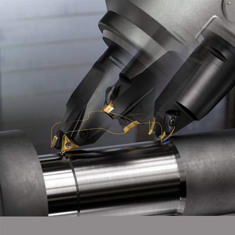 Sandvik Coromant's PrimeTurning all-direction turning
As to the benefits, when turning a hub made from cast steel (SAE/AISI 1045) on a Gildemeister CTV 250 turning centre, a machining company in Brazil used the same cutting speed (300 m/min) as used with a competitor insert, but the adoption of the latest all-directional inserts allowed feed rates to be increased from 0.25 to 0.4 mm/rev, and depth of cut from 1.5 to 3 mm. The result was a 59% increase in productivity and 55% greater tool life. With over 120,000 hubs a year being produced, the positive impact was considerable.
Sandvik Coromant has developed inserts and toolholders (including a two-position roughing and finishing tool to avoid tool changes, picture, next page), as well as its PrimeTurning CNC code generator that produces output compatible with a wide variety of CNC machines (Mastercam CADCAM integrates PrimeTurning support). But the machining technique is not suitable for all, so the company invites users to use its online test at https://is.gd/ogusom.
Staying with turning and last September’s EMO exhibition in Hanover, Germany, revealed a cutting technique that employs a more dynamic approach, as perhaps indicated by its name, Rollfeed. Originated by German company Vandurit, the method is described as “a quantum jump in [the] evolution of turning”. Using either the B-axis of a CNC turning centre or the special Vandurit toolholder located in a driven tool position (synchronous threading capability required), the circle section cutting edges of the special inserts are rolled during the cutting of rotationally symmetrical surfaces of any shape, both internal and external (main image). A compensating offset is generated for X and Z axes as the tool itself moves in X and Z, and as the insert is rolled (multiple videos: https://is.gd/fujaya). Open Mind software supports Rollfeed turning (‘hyperMILL rollFEED’ turning strategy). As with PrimeTurning, a single insert allows for the machining of three surfaces in an undercut, for example. Indeed, complex contours can be cut with a single insert (currently two styles).
A reduction in machining time of 90% is claimed, along with very long tool lives that reduces tool change requirements – Vandurit characterises this as “an up-to-90% reduction in tool consumption”. Pilot customers are using the technique for hard part machining, cast iron and sintered metal processing, and the company is developing inserts for softer material machining, according to Jürgen Klose, who is responsible for the development of Rollfeed. Machine tool maker Emag is an early adopter – all its machines can be equipped or retrofitted with the technology, with its VL and VSC machines having it as a standard option. Visitors to MACH 2018 (9-13 April, NEC, Birmingam – www.machexhibition.com) will be able to discuss the technology with Open Mind (stand H17-620).
Moving onto milling, specifically finish milling, and the combination of latest design barrel cutters from WNT (part of the Ceratizit Group) and supporting CADCAM software from Open Mind (5-axis tangent plane cycle) is claiming a reduction in machining times of up to 90%. The two technology specialists put on a demonstration last November at the Advanced Manufacturing Research Centre with Boeing, located in the Sheffield City region.
As we wrote in Machinery’s November 2017 issue (full article: https://is.gd/hihewa), instead of straight sides, barrel cutters have large radii; cutting with the side of the tool being the manner of application. In the case of conical barrel, there are two possibilities. These feature a straight shank that leads into a taper of either around 20° or a more severe one of around 70° (included angles in both cases), then into the radius. In the former case, this allows for a much larger radius on the side of the cutter, even up to 3 m. Old style barrel cutters would be limited to up to 50 mm or so. “That is the difference between the ‘old school’ cutters and the new,” Open Mind Technologies UK’s managing director Adrian Smith said at the event.
The larger the radius, the greater can be the step-down versus a ballnose for a similar cusp height or the better can be the surface finish for the same step-down, or a combination of both. Higher step-down without loss of surface finish is “the big win”, said WNT business development manager Adrian Fitts at the same event. One requirement is that the larger the radius, the greater the need for a high quality machine tool to make sure that witnesses where cutter paths meet are minimised, but there is no greater spindle power requirement.
At the November event, finishing an open-sided pocket in an aluminium component using a 16 mm diameter 20° conical barrel cutter for the sides and a 10 mm diameter 70° conical barrel cutter for the bottom was contrasted with scan-cutting using a 6 mm diameter ballnose cutter. The difference between the two was massive; four minutes for the barrel cutters and 41 minutes for the ballnose. Another event to highlight the benefits will take place at the Training 2000’s Advanced Manufacturing and Automation Centre (AMAC) in Blackburn on 26 and 27 February – visit www.training2000.co.uk/events to sign up (event is now in the past).
Finally, the latest development from Sandvik Coromant is Y-axis parting-off (video:https://is.gd/ahudol). In essence, it is an exploitation of a mechanical advantage conferred by an axis positioned at right-angles to X (Y-axis), complemented by a new tool design. In conventional CNC lathes, parting-off from the rear with a tool having the tip on its top side is achieved using X-axis infeed and clockwise spindle rotation. This directs cutting forces downwards, through the parting blade’s height:
a large blade height relative to the width is the way this is countered. In Y-axis parting, the blade enters from below a counter-clockwise rotating part, with cutting undertaken on the ‘front’ of the insert (the insert’s top surface has been rotated 90°), thus directing force along the blade’s length.
Sandvik Coromant says that FEM analysis confirms increased blade stiffness of six times, compared with standard designs, meaning that blade deformation is as low as one-sixth that for standard blades. In the online video, a feed rate three-times higher is demonstrated as possible and resulting surface finish appears better.
Parting diameter capacity is also boosted with this new method. A pre-test confirmed a 50% increase in overhang was possible when parting-off a conventional 120 mm diameter bar at the maximum feed capacity of the insert, with a 300% productivity increase achieved with no process security complications. In a customer test case, Y-axis parting-off successfully replaced bandsawing for a 180 mm diameter Inconel bar. And Sandvik Coromant’s production unit in Renningen, Germany, is using Y-axis parting-off in the production of CoroChuck 930 and other basic toolholders, with a reduction of five to 15 seconds/part in the case of CoroChuck 930 units.
Clearly, while machine and tooling performance continually improve, the above innovations deliver additional welcome productivity bonuses.
Box item 1
Esprit ProfitTurning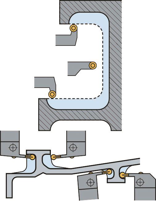 Situations in which ProfitTurning can be applied
When using traditional turning methods on heat-resistant and hard materials such as super-alloys, large engagement angles and inconsistent chip load can occur at both tool entry and exit, explains Esprit author DP Technologies. Traditional turning methods can cause adverse effects during the cutting process, such as heavy tool load, high and irregular cutting forces, vibration and poor chip control.
Maintaining a constant chip load is vital to machining high quality parts and extending tool life. In particular, if chip load is too low or too high, faster tool to wear faster can result. Resulting wanted outcomes may include chips so large that they cannot get out of the cutter’s way fast enough.
ProfiitTurning, then, eliminates the adverse effects of traditional turning methods, but incorporates several techniques. Key is its use of round inserts or the full radius of groove tools to achieve higher feeds rates, in order to maintain a constant or near-constant chip load. When machining grooves, a constant feed rate is employed and ‘roll-in, cut and roll-out movements’ follow, with cutting in a single direction. In the case of undercuts that narrow, this first approaches gives way to trochoidal turning at some point, until the trochoidal radius is reached, leaving rest material. A further possibility for plane diameter turning is both direction cutting, with direction reversal at the end of each cut eliminating normal tool withdrawal.
Against traditional zig-zag turning, ProfiitTurning delivers a 25% reduction in cycle time and tool life three times better, as inferred by measured drawn spindle power. In a test on a part machined on an Okuma CNC lathe (video: https://is.gd/suyowe), a 41 sec cycle became 21 sec. (ProfitTurning white paper: https://is.gd/wipiya)
Box item 2
Trochoidal milling, a refresher
According to Emuge-Franken, Trochoidal milling is a cutting strategy that involves the overlapping of a circular cutting path with a linear movement, in effect converting slot milling into contour milling. Trochoidal milling is particularly suitable for difficult-to-machine materials and thin-walled components. The resulting small contact angle reduces heat generation during machining, with lower thermal stress resulting in higher tool life. Emuge, along with others, developed cutters specifically for this technique (Video: https://is.gd/hadiga).
Box item 3
Citizen Machinery’s Low Frequency Vibration (LFV) technology
Machine tool makers also originatemachining techniques, one of the most recent being Citizen Machinery’s Low Frequency Vibration (LFV) technology, which is gathering orders worldwide. An answer to the problem of stringy swarf, it uses standard tooling but employs axis back-and-forth motion (in X or Z) that interrupts the cut, so breaking swarf into chips. Full article here: https://is.gd/fexewu. Star Micronics’ High Frequency Turning is similar, but is a CNC macro, likewise Tornos' Active Chip Breaker, also a CNC macro.
First published in Machinery February 2018


