
The event follows Faro’s acquisition of laser projection and metrology company LPT Technologies, of New Hampshire, in September.
One of its products currently undergoing a Faro makeover, for release before April 2017, is to be called the TracerM. It shines a laser on parts to be assembled, displaying instructions or indicating positions of holes, brackets or other features by casting a net of 0.5 mm-thick green lines over the part – not just in plan but with depth as well, and in three dimensions.
The projected lines are taken from a CAD drawing, reduced to a wireframe image, and are displayed using a 5 mW laser projector via a pair of mirrors controlled by high speed servomotors. Since the laser refresh rate (up to 80 Hz) is too quick for the human eye to follow, the laser beam’s travel around its 3D path appears to the eye instead as a static glowing laser template.
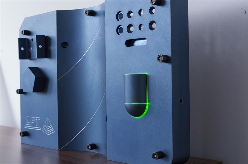
The TracerM employs a fast-moving laser to project feature details in three dimensions onto this sample target (photogrammetric reflectors are held in raised bolts).
The machine can project an image in a plane that measures 60° wide in X and Y to a maximum distance of about 15 m (at which it can handle a 15 m by 15 m part). Maximum depth of line projection around the part is about 5 m (± 2.5 m). Projection accuracy is said to be ± 0.25 mm. The machine uses a set of retroreflective photogrammetric targets placed on the part, minimum six, to locate the part in 3D space.
Building on the TracerM, a new model planned for launch later this year will offer not only projection but also near-instant in-process verification, so that an assembly operator would receive confirmation that a bracket was placed in the right orientation on the part by comparing it to a reference CAD model. To do this, the forthcoming TracerSI employs a feature-recognition algorithm that scans the part and automatically identifies holes, interior or exterior corners, corner radii, intersections and fasteners. Feature tolerances are user-defined.
For example, the device could determine the location of a countersunk hole in a part: the software scans the hole and fits an ellipse to the image. The measured data is compared to the CAD data and, based on pre-set tolerances, a pass or fail is issued. Another example is in carbon fibre lay-up; the system can discern the orientation of the fabric, based on the pattern of light reflected from the weave.
The system automatically fits a line parallel to the fibre direction and determines its angle, again issuing a pass/fail determination. There are additional process controls, helpful for performing lots of part scanning, too: the software allows users the option of rescanning a failed item, or resizing or moving the scan box.
The system creates an image by reading data along a raster scan path, building up a pixel map based on time intervals. Process steps involved are, as one might imagine, fairly complex, involving digitisation, digital signal processing, image and geometry processing, edge detection and point cloud validation. When launched, this functionality will be available via Faro’s recently-acquired metrology software platform BuildIt (www.builditsoftware.com).
Most advanced of all is a non-contact laser-based Lidar product, five years in development, that combines scanning, projection and in-process feedback. It scans a part at a rate of up to 100,000 points/sec, generates a point cloud model, converts it into a 3D shape, compares that to an existing CAD file, and determines variance between the two. So far that’s fairly standard; Machinery saw exactly that demonstrated at the Faro service centre, displayed in a false-colour on-screen image, having been produced in seconds at close range by a Faro Edge arm with laser scanner connected to a Vantage laser tracker. But the Faro VectorRI goes one step further: by turning the variance into a contour map, it projects back on to the part, in fact on top of the variance itself. The VectorRI does this essentially by focusing on the variance feature alone, fitting the point cloud, creating a surface mesh, making a topographical map, creating laser projection data and then projecting the image.
The great advantage is clarity and simplicity: shopfloor workers can see the problem with the part, on the part, without any guesswork or secondary measurement required. The application described by Roger Waldock, global sales director of the new division of Faro, 3D laser imaging and factory automation, was in aerospace, specifically large composite carbon-fibre fuselage sections, vertical stabiliser or wing skin parts that can measure up to 10 m long or 6 m wide. When cooling after the autoclave process, composite parts can deform. To look for springback deviation problems prior to moving the parts to assembly jigs, workers currently have to go through the time-consuming process of setting up pencilled grids on the part and taking points across the grids using a laser tracker. Or they would need to inspect the part on a coordinate measurement machine, if a large-bed model could be found. The VectorRI machine would be able to pinpoint areas of variance quicker and more easily than these methods, and show workers where to perform further rework or build-up operations.
FUTURE POTENTIAL
More mainstream uses will be found for this brand-new technology over time, on the factory floor, it is believed. Add Waldock: “We probably don’t even know a tenth of the applications that this could potentially be used for in the future.”
Launch is planned for after June 2017; in fact, the 10 units currently being built are shipping to early adopter customers for final market feedback before then; the company then plans to make an initial batch of 50. The current package price of US $295,000 (£231,000) is expected to drop with higher volume manufacture.
Both of the latter products, shown at the Advanced Engineering show in November, are bristling with enabling technology. They feature digital beam steering technology providing 20 times better positional accuracy than the TracerM, offering about 1 million steps. To survey a target with laser light, they rely on a photomultiplier tube so sensitive it can pick up reflected light that is up to 100 million times dimmer than the laser source. Also important is the digitiser used to convert an analogue light pulse signal into digital data; the model used in the VectorRI, capability 100 giga-samples/sec, has been newly released from a military application: ground-scanning in an F-15 fighter aircraft.
The fundamental laser technology involved in the three machines was developed at Boeing in the 1990s; the company still holds those patents. And before founding Laser Projection Technologies in 1996, president and CEO Steve Kaufman worked on the US military's Star Wars project (firing lasers at space objects, such as rockets). Employing 22 people when it was bought by Faro, it holds eight patents; six more are pending.
In announcing the acquisition of LPT in August, Faro president and CEO Dr Simon Raab said: “We believe LPT’s proprietary imaging laser photogrammetry and imaging laser radar technologies have tremendous potential to disrupt the market by establishing a new class of high speed laser measurement with advanced 3D imaging capabilities, and we will focus our integration efforts on rapidly leveraging this potential.”
TEXT BOX
An alternative
The Nikon Metrology (01332 811 349) MV331/351 Laser Radar also provides automated measurement of objects, in this case, at a distance to 30 or 50 m, without requiring targets, retroreflectors or probes. Its vision scan capture mode records up to 2,000 points/sec. Like the TracerSI and VectorRI systems, it performs automatic feature, edge and trim measurements.Video: https://is.gd/ticajo
This article was published in the January 2017 issue of Machinery magazine.

