
International support manager and application engineer Craig Chester’s advice is to avoid 5-axis simultaneous activities unless absolutely essential. Keep rotary axes (A/B and C) locked, if possible, either undertaking so-called 3+2 (positional) or 4-axis machining.
In fact, 3+2 machining is far more common than 5-axis simultaneous machining, he says, and for good reason. Its use allows tool access, so avoids multiple set-ups, plus shorter tools that support faster cutting and deliver superior surface finishes. The latter is also aided because the machine will be more rigid if only three axes are moving versus five or even four.
Other benefits for 3+2 machining are: it’s simpler and therefore allows faster calculations for CAM software; it is easier to understand where collisions might occur; the movements of the machine are more predictable; and the program will likely run faster for a given part on the same machine, because the CNC is processing less data.
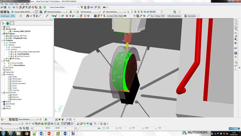
In constructing a 3+2 programme, employing a 3-axis approach and seeing where collisions occur can be preferable. Take the part in the image below, which has steep and shallow surfaces. Clearly, the tool shank will collide with the steep surface, but we can run it and allow collisions (and near-misses) – these will be listed, while the colliding element will turn red on screen (below).
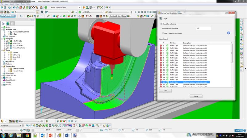 Collision checking reveals what is happening where - users can interrogate any instance listed
Avoiding collisions using the extra two rotary axes can be accomplished by the user manually via Dynamic Machine Control (below). This allows head axis angle positioning (including specified increments, if a machine has this limitation) and then dragging the tool/head around the part to confirm a collision-free operation. In doing this, however, with the A/B and C axes angled, machine axis travel limits may be breached, due to the extra travel required to position the head. This will be indicated. But assuming all is well, new code can be calculated “in an instant”. Asymmetric heads are also accommodated by PowerMILL, with the user able to choose which side approaches the workpiece – vertical or inclined.
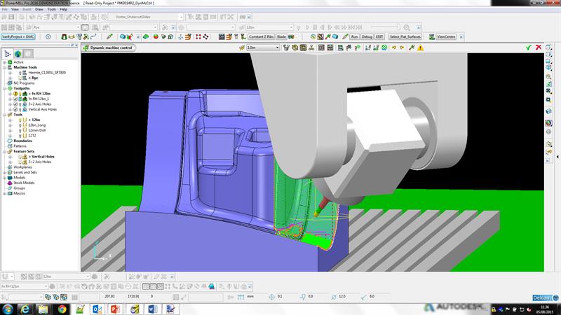 Dynamic Machine Control allows the head to manually repositioned, with new code produced "in an instant"
In terms of machining strategy, for this part at this stage, Delcam’s ‘steep and shallow’ finishing strategy is being employed. This combines constant Z machining, otherwise called waterline machining, for the steep surface, and for the shallow surface raster (zig-zag across, where advance is at 90° to the zig-zag motion) or 3D offset (collapsing offset), where an essentially circular in-to-out or out-to-in motion, is employed.
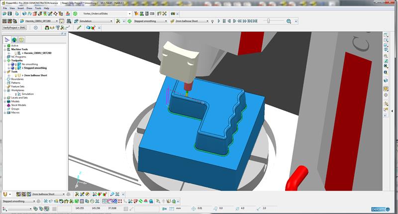
Chester says he is not a fan of the 3D offset strategy when finishing; it is more efficient, yes, but it leaves more tool marks, as there are more corners that see deceleration and so tool relaxation into the material. Raster lifts the tool off, turning outside of the cut area, and then ramps back into cut in the opposite direction, reducing surface marks – but this is not possible at a vertical wall, since there is no ‘outside the cut area’ in which to turn.
Now, it is possible to improve 3D offset machining strategy by employing ‘smoothing’ and ‘spiral’ attributes. This gives fewer lifts and corners, but this will result in a larger cusp height when using spherical tools; yet most people would use smoothing and spiral, because the positives outweigh the negatives, Chester advises.
Why not always tick the option for smooth and spiral? Well, let’s take the case of constant Z machining around a boss, which would become a spiral if ‘smooth’ and ‘spiral’ attributes were ticked. The choice for best performance depends on the CNC. Older models will machine slower (regardless of programmed feed rate) in 3-axis machining than they do for 2D machining. It is also the case that older CNCs may prefer arc-style NC code output (G03/04), rather than the more voluminous straight line (G01) equivalent – they may not be able to process the greater amount of straight line data quickly enough and so suffer stutter. The upshot of this is that a 2D, arc-style move on an older CNC at constant Z will be faster and the surface finish better than for a 3D spiral, straight-line approach, suggests Chester.
For modern CNCs, this situation is likely reversed, as the size of the CNC program is not an issue (straight line output results in much more data), while straight line output may be preferred versus arc-style. In fact, the control is probably changing the multiple straight lines into fewer splines internally, prior to these being processed to drive axes’ movements. Arc NC data may be slower to process, particularly arc-line transitions.
Another data output/CNC issue relates to program positional point density, particularly on curved surfaces. Where a chordal tolerance figure is set and surface curvature varies, points will be closer together in areas of higher curvature. This results in non-uniform point distribution. Older controls were happy with this non-uniform situation, due to their lower processing requirement, says Chester, but modern units are not and tend to produce stuttering toolpaths. The answer in PowerMILL is for the user to set a maximum point distance and chordal tolerance. Points may get closer in order to meet the chordal figure, but they will never get larger. The result on modern controls is a faster, smoother machining cycle – a 39% cycle reduction was achieved in Delcam’s workshop – plus a superior finish. This is a “big deal for PowerMILL”, emphasises Chester, particularly for mould tool makers looking for the highest quality surface finishes.
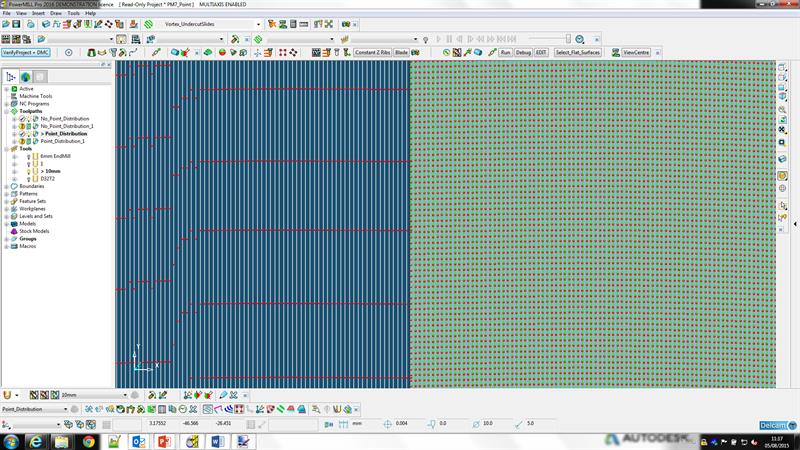 Left, original point distribution; right, point distribution controlled
These points about strategy attribute choices and controller preferences are generally applicable, not only to 5-axis machining, of course. To discover what your machine likes and dislikes, and so be able to apply the right parameters, Delcam has its Machine DNA product, by the way, which is currently undergoing further development to make it easier to apply.
Now back to collision avoidance and our initial part. It is possible to have the machine take automatic action to avoid collisions, either by leaving material on or by having the rotary axes adjust themselves to avoid collisions. For the latter, figures for lead (tool inclination in direction of travel), lean (tool inclination at right-angles to direction of travel) and smoothing can be employed to adjust transitions, but this may not lead to a perfect solution.
Take pencil milling/rest milling around the base of a boss that has undulating surfaces (below), with lead set at 0° and lean at 45°, excessive rotary axis motion occurs. The solution here is smoothing by selecting [a] splining while still remaining in full 5-axis simultaneous mode or [b] adopting 3+2 machining and staying at a constant rotary axes setting where possible, which will result in, in this case, four 3+2 program segments with a smooth simultaneous 5-axis transition between each.
 Pencil milling of this part could deliver excess rotary axis motion, so smoothing is required
Another area where excess rotary axis movement can occur is where there is a lot of detail overlaid on a smooth, curved surface, such as a spectacle frame mould (below). Even if lead/lean of 30° is applied, as opposed to 0-0, there would still be too much rotary axis motion. To avoid this, a drive curve that is identical to, but offset from, the underlying smooth surface is created, with the tool asked to reference this, adopting a 0-0 lead/lean setting for a spherical tool. In this case, we get a smooth 4-axis cut, in fact.
A drive curve allows for smooth machining of highly detailed surface
As mentioned earlier, a 2-axis head might break axis limits when orienting a tool at an angle. A trick to avoid exceeding X- or Y-axis travel is the use of the ‘Polar Milling’ cycle. This sees the C-axis rotated instead, with either X or Y locked; rather like turning but with a milling cutter. An example might be a wheel (below). Chester highlights that others may achieve this via a post-processor, but advises that once outside the CAM system you lose all its intelligence, as regards collisions or over-travel, for example.
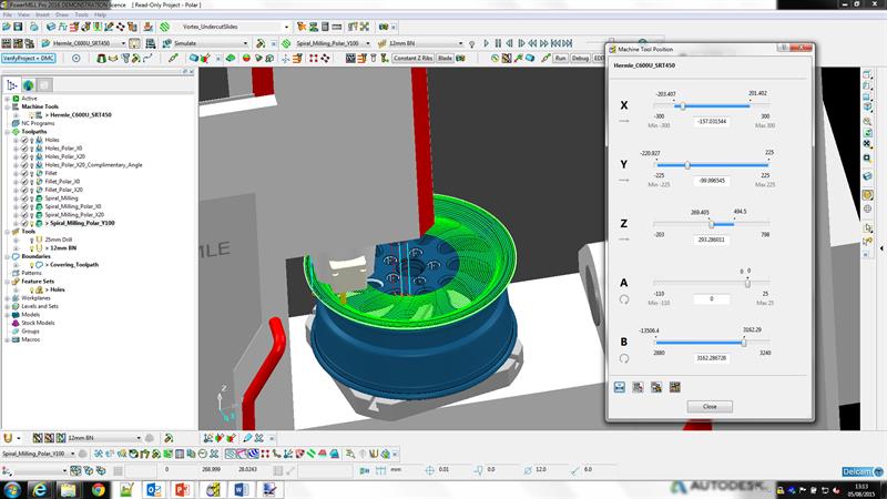 Polar Milling can be employed where axis travels would otherwise be breached
An example of where 5-axis simultaneous machining is definitely required is swarf machining of a swept surface. This see the side of the cutter used to machine the surface, avoiding multiple cuts. Delcam can employ the top and bottom of surface wire-frame control method but, for surfaces that mathematically allow it, prefers to let PowerMILL automatically maintain surface contact along the cutter. Chester says that while most CADCAM systems will have swarf machining, it is a challenge to perfect – any jerks or dwells will result in a far worse finish than would be achieved by point machining, so the user must set program parameters correctly to avoid machine dwell/jerk.
Another area where 5-axis simultaneous is necessary is in machining, say, a car body prototype using a flat-bottomed mill having radiused tips. The use of a flat-bottom tool reduces the number of required passes versus a spherical tip, so saves much time, and produces a better surface finish. Here, the tool must be kept at the correct lead and lean. Turbine blades would be another area where flat-bottomed tools might be so applied (below). And finally, drilling at multiple angles around a part can employ simultaneous 5-axis to support positioning or, in this case, the process could be split into multiple 3+2 portions.
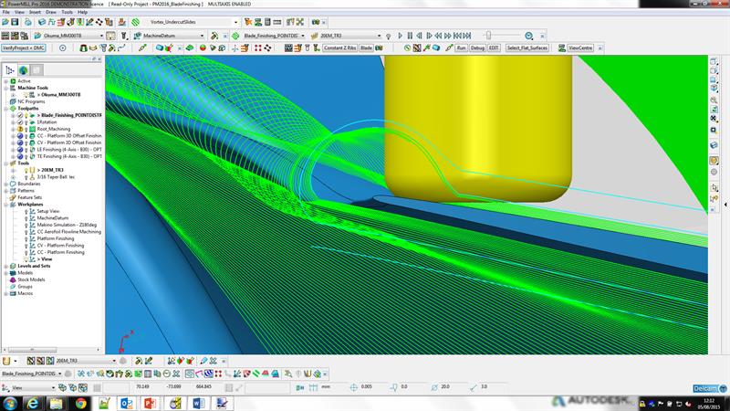 Cutting a turbine blade using flat-bottom tools requires lead and lean settings to be maintained, requiring 5-axis simultaneous machining
Box item
Five-axis strategies without limit
Delcam’s PowerMILL does not, for the most part, have specific 5-axis simultaneous/5-axis positional strategies. Where sensible, so not for drilling or boring, the application of either is a choice in a strategy’s attributes. There are two specific 5-axis strategy options that are additional to the PowerMILL 5-axis package, however: ‘Blisk, Blade, Impeller’, and ‘Cylinder Head Porting’. It is also the case that 5-axis machining of either flavour is not restricted to spherical tools; PowerMILL can employ flat bottom, radiused insert milling cutters and even barrel-shaped cutting tools.
First published in Machinery 5-axis machining supplement, September 2015


