
The University of Sheffield’s AMRC is one of 11 partners in the three-year Twin-Control project that started in October 2015, as Machinery previously reported (https://is.gd/kocoja). With the €5.6 million project scheduled to reach its conclusion in October of this year, the AMRC, along with a number of partners from the Twin-Control consortium, held a dissemination workshop to share recent developments.
The aims of Twin-Control include the development of a system that provides a better estimation of machining (milling) performance than single-featured simulation packages. This holistic simulation model will be linked to real machines in order to update itself, according to their actual condition, and carry out control actions that lead to performance improvements.
At the workshop, Luke Berglind, a researcher at the AMRC, provided a key update on the Twin-Control process model based on virtual manufacturing, specifically relating to the ‘cutting force model’, a key element of the project.
“During machining, two interactions occur between the tool and workpiece; one is geometric interaction that removes material, and the other, due to that material removal, is force interaction,” he said. “The reason we are interested in simulating force is to better understand machine loading and dynamics, as well as the effects of vibration, to ultimately drive process improvements.”
There are many factors to consider in calculating cutting forces, including material characteristics, spindle speed and many aspects of the tool, such as geometry, orientation, feed rate, engagement direction and cutting speed. To compound the complexity of the task, a number of key parameters change as the cutter progresses through a typical machining cycle.
CUTTING FORCE CALCULATION
“At the AMRC, we’ve developed a force model to determine the cutting force, based on how the tool is interacting with the workpiece, as the tool’s orientation and feed speed change at every step in the toolpath program,” said Berglind. “This discrete model uses a tool mesh, with each element comprising some aspect of force characterisation. By having all of these elements acting in unison, it is possible to sum up their characterisation frequencies and combine their velocities. We can then take all of the elements that are cutting at any one point in time and move them together in a particular direction, and come out with a total cutting force.”
Using the AMRC’s force simulation, it is possible to see the cutting forces as the cutting edge rotates through a particular region. Even rapidly changing parameters within highly dynamic 5-axis cycles can very quickly be accounted for in the simulation.
“As part of the Twin-Control project, we have performed many 5-axis static force experiments and I can report very good results comparing measured forces to simulated forces,” said Berglind. “However, we have also done a lot of dynamic force modelling. This means we can also predict whether chatter is likely to occur at a specific engagement between the tool and workpiece.”
For dynamic 5-axis machining, because of the high variability in parameters, the AMRC has developed what it calls the stability roadmap. So, stepping through a part program, it is possible to predict a range of spindle speeds that would be stable or unstable. In addition, different regions of parts will be highlighted as showing higher or lower stability cutting conditions.
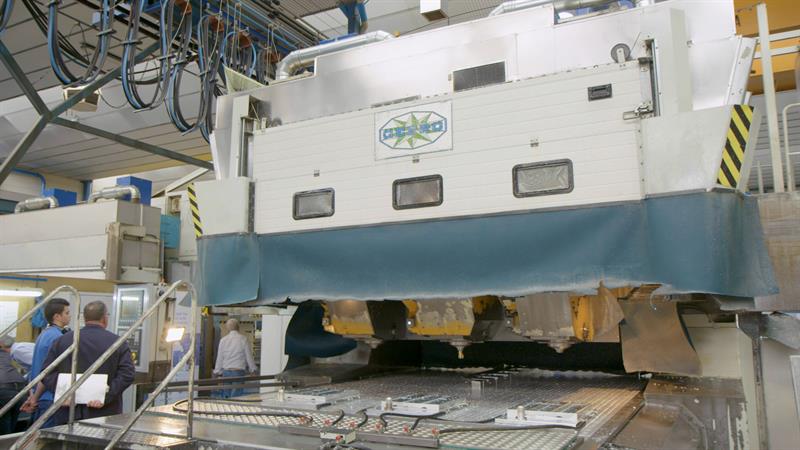
A Gepro machine used by Masa Aerospace is a real life test bed for Twin-Control
“As we select a specific spindle speed for one operation, we can follow the roadmap to find regions on a component where we expect to see chatter,” explained Berglind. “Again, we have had good success in actually witnessing chatter on parts in the regions [and at the spindle speeds] we predicted.”
Another aspect of the AMRC’s research relates to surface location error. Wherever there is interaction between force and a dynamic system there will be vibration. In machining, these vibrations cause the tool’s cutting edges to diverge from the precise location specified in the program. As a result, an unexpected surface profile (roughness) is left behind.
Said Berglind: “If we model the cutting edge, take our force model and apply it to the dynamic system, we are able to simulate the tool’s vibration as it moves through the cut. By tracing the cutting edge as it is spinning and vibrating simultaneously, we get a much better picture of the surface we are actually leaving behind. In trials, we’ve been able to show that the simulated vibration on the part and the corresponding surface shape matched very closely what we measured on the component.”
At Siemens company Samtech, a Twin-Control consortium member that is driving the ‘virtual machine work element’ of the project, the AMRC’s cutting force model is integrated with Samtech’s full machine model, known as VMT (virtual machine tool).
“We have full integration with ourselves, CADCAM software specialists ModuleWorks and Samtech to model the tool position on the workpiece and obtain cutting forces throughout the entire part, based on how the machine is moving. These forces then go back into the full machine simulation,” Berglind explained.
SIMPLIFIED SIMULATION FOR SPEED
In a further interesting development, the AMRC has created a simplified version of this model as the full machine simulation takes some time to run, typically a few hours. However, for those not requiring that level of detail, a model has been devised that allows a quick check on the cutting forces or chatter circumstances. The model takes in a part program, tool geometry and stock material, with a full component program being run through the simulation in just a matter of minutes.
Finally, the most recent place that the AMRC has applied its force model to is online simulation. Instead of simulating individual moves in a part program, one by one, the online application makes it possible to actually simulate the cutting forces in real time with the machine tool.
“In collaboration with ModuleWorks and Artis, we have developed the capability to stream data from the machine control directly to our simulation,” states Berglind. “Artis, a Marposs company, takes measurements on the real world machine using its Genior Modular system, an automatic tool and process monitoring unit. These measurements provide us with information on the tool’s position and spindle speed. On the simulation side, we take this information and run it through our model. So, we have a virtual part in our simulation, virtually moving our cutters following the path of the actual tools. Whenever the path of the cutter interacts with the virtual part, we use the data produced to run through into our force calculation. There are a couple of things we have to predefine: the tool geometry and the material stock data. We then plug in our inputs from the actual machine so that – in real time – we can compare the measured forces versus simulated forces. We can also look at things like our chatter predictions, again in real time. So far, the results have been pretty good.”
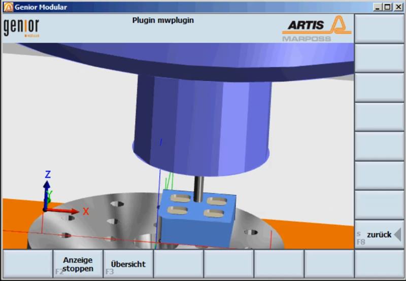 Genior Modular system performing monitoring on a Huron machine
Right now, the AMRC says this is really early capability, with practical uses for the system currently under consideration. “We have tight integration of what the machine tool is doing and what it is simulated to do – in real time,” said Berglind. “Ultimately, it will be appealing to all those interested in knowing what the machine ‘should’ be doing. As soon as machining starts, we use feedback from the machine to update our model so that it better reflects what is actually happening. Then, once we have our model calibrated, so to speak, we can continue to run our simulation and compare it with real life machining. We can then start to look at things like tool wear monitoring.
“Another potential benefit relates to tool changes,” he added. “If we put a new tool in, say halfway through a part, we take a measurement and make sure our simulation is up to speed and is accurate. Then we can set process boundaries in real time. We know what the forces should be, and we know what the torque should be, so as long as we stay in that range we should be happy with the process. If we start to see any drift, we can investigate the cause.
“What we don’t have the capability to do right now is correct in real time. At present, it’s a one-way feed from the CNC to our simulation. Also, our roadmap only currently considers tool dynamics; eventually, the next step will be to include component dynamics, which would show the roadmap in much greater detail as material is removed from different areas of the workpiece.” ■
Extended version from here:
Twin-Control consortium partners
[] Mikel Armendia, a researcher at the Automation and Control Unit of Spain-based technology centre IK4-Tekniker (he is also the co-ordinator of the Twin-Control project as a whole), spoke about the development of software models intended to: shorten the time required to get machines working as intended (target 10% time/cost reduction); reduce the time needed to get processes working as intended (20%); generate process improvements through model-based control; reduce energy consumption; improve machine tool reliability; and reduce TCO (total cost of ownership). Industrial validations are currently in progress at Renault’s plant in Cleon, France, and at the site of another consortium partner, MASA in Spain, which is using multi-spindle machines built by Gepro Systems to produce structural aerospace components.
[] Frederic Cugnon, flexible multibody dynamics expert at Siemens company, Samtech, elaborated on his efforts to deliver advanced mechatronic modelling of machine tools and machining processes. To properly simulate high speed machine tools, it is crucial to build models that represent the flexibility of all components and their interactions. Samtech’s solution considers FEA models of the parts connected together by a set of flexible kinematical joints. The proposed technology is being applied to build a mechatronic flexible multibody model of a Comau machine. This approach allows comprehensive simulation capabilities for virtual machine tool prototyping in working conditions. The resulting Twin-Control simulation package is intended for machine tool builders and users (to improve their processes). In both cases, the virtual model will avoid performing many costly physical tests.
[] Reliable and continuous monitoring of all use-case machines is one of the most important tasks in Twin-Control. Here, Dr Tobias Fürtjes MMS research project manager at Artis, and task leader for Twin-Control monitoring infrastructure, presented on local process monitoring for Industry 4.0. The company’s solution allows Twin-Control to provide 24/7 cloud-based monitoring for fleet-level process analysis, as well as analysis across different machine tools, factories, processes, products and countries. The basic device is known as Genior Modular, which monitors real-time data from the machine control, and receives and processes real-time data from additional devices. The system is fully automatic, and no parameter setting or specialist knowledge is required. Additional modules include OPR (Offline Process Recorder), an intelligent storage isle that connects to the cloud platform and allows local process analysis. There are 12 use cases across Europe.
[] ModuleWorks is focusing on material removal simulation and visualisation of measured/acquired data. Senior software developer Denys Plakhotnik outlined how consortium partners access ModuleWorks process data as an interface to the material removal simulation, thus advancing simulation detail and accuracy. For instance, the force model developed by the AMRC employs ModuleWorks’ geometry engine to compute cutting tool engagement information and, subsequently, cutting force data.
First published in Machinery May 2018


