The non-destructive internal measurement of additively manufactured (AM) metal parts can be undertaken using X-ray computed tomography (X-ray CT) scanning. That process is not without its issues, however, so researchers at the AFRC are taking a look at the use of phased-array ultrasonics (see box, below) as a potential alternative. Early results are encouraging.
Daniel McMahon, metrology and digital team leader at the AFRC, is one of those involved in the multi-partner effort. The metrology team supports other research across the AFRC by providing supporting measurement services, also offering this as an external service, while the digital team is concerned with investigating Industry 4.0 technologies, such as advanced visualisation, virtual and augmented reality, machine connectivity and the Industrial Internet of Things (IIoT) and automation.
McMahon explains the challenges of inspecting additively manufactured parts: “The first challenge is comparable to when you are traditionally machining the part, where you rely on the machine to produce an even surface, and whether that’s a flat or freeform surface, you still get a smooth surface. In the case of additively manufactured parts, you get an undulating and uneven surface, which poses a challenge to contact measurement such as a coordinate measuring machine (CMM) that samples the surface using a probe and where there is an assumption that anything between the sample points has uniformity and that you are getting a true representation of the surface.
“When it’s an AM part, it’s similar to what we do with forming and forgings [at the AFRC], where you form the whole surface of the material in a more unique way and where there is more scope for freedom. In such cases, discrete-point-based measurement can sometimes lead to odd results that are not a true representation of the overall surface; so that technology maybe isn’t the best for an AM part, unless you’re doing some subsequent machining on the surface.”
EXTERNAL FEATURES SCANNED
For external features, non-contact measurement is employed, with the AFRC using optical scanning that employs structured blue laser light. The organisation has a GOM (https://is.gd/oherag) ATOS TripleScan III/rotary table that it employs for such purposes. This captures a dense point-cloud of thousands of points that allows for the creation of a 3D model of a part, with this model then available to be interrogated at any location to reveal the associated dimensions. The GOM system is accurate to within 10 micron and boasts repeatability of 5 micron (YouTube: https://is.gd/inexof).
For internal measurement, a further challenge is the greater amount of geometric freedom available with AM parts. McMahon again: “There is more of a free rein to create internal features, so more comparable to a casting process where inserts are used within a mould to create an internal feature. You can’t measure that internal feature, but at least [for castings] you’ve got the insert that you can dimensionally assess. With AM, there’s much more freedom to create internal features, without any inserts; you can print whatever you want, so there will be internal features that you can never access once the part is finished; that you can never really inspect using traditional methods. That is where the challenge is. How do we inspect those features contained within a part where there is no line of sight or physical access?
“A variation of that challenge is where, if you consider AM as like printing text on a sheet of paper, sometimes the nozzles can get blocked or something can change in the process that leads to the text or images coming out a funny colour, or there’s missing lines of text. If that happens in AM, you’ve not got something that’s a funny colour or some text missing, you’ve got some weakness in a part or a fully developed defect, such as an inclusion, and that can be a stress raiser. That needs to be assessed to understand whether the part can undertake the function for which it was designed.”
Okay, but what’s the issue with X-ray CT-based inspection? In this process, multiple X-ray slices of parts are taken to build up a 3D image of the internals of a part (or person, in the case of medical applications) and the High Value Manufacturing Catapult, of which the AFRC is member, is indeed studying this technology, but there are many variables involved, as McMahon points out: “Results can vary from machine to machine and from operator to operator. That is something that really needs understanding, with best practice then communicated.
Of course, X-rays are quite harmful, so measurement is undertaken within a lead box, meaning scalability isn’t great, while it also takes a lot of power to go through a metallic component. So its application to larger structures is not really feasible, while the equipment is very expensive and ongoing running costs are high. Phased-array ultrasonics is about one fifth the cost of X-ray CT, has lower running costs and it is scalable.”
Phased-array ultrasonics are already used in industrial NDT applications, but for dimensional measurement that technology is not adequate, hence the collaborative research. Says the team leader: “We have been using a new method of phased-array ultrasonics, which was developed by the University of Strathclyde’s Centre for Ultrasonic Engineering (CUE – see later). This allows us to do a full matrix capture that gives us a lot more data than would normally be captured, so the [computer] processing power required is quite high and the processing time quite a bit longer than normal.”
But with more data comes greater resolution and, hence, the ability to measure to, at the moment, sub-millimetre accuracy level, which McMahon says obviously has to be improved upon.
HIGHER RESOLUTION TARGETED
By way of comparison, the resolution for X-ray CT inspection is down to 10 micron, but to confidently interpret what size something is with X-ray CT, a reference artefact within the measurement zone is required, because interpretation of the visual results is absolutely key. In addition, the X-ray images must be clear and sharp, which depends on getting a number of settings correct. The central nut to crack with the ultrasonic method is to gather data at higher resolution, confirms McMahon, the analysis stage is already well developed.
The overall inspection time for a similar part would either be the same as with CT or phased-array ultrasonics would have the edge, he suggests.
CT scanning takes a long time, hours; the ultrasonic method is far faster, but then there’s the data processing time that adds to the total overall time. It is the precise positional control and manipulation of a standard ultrasonic probe plus this data processing that are the central elements in the research.
The computer algorithms employed to analyse the data are the intellectual property of CUE, a department that has more than 30 years of experience in this area. CUE is also a founding member of the UK Research Centre for Non-Destructive Evaluation (RCNDE – www.rcnde.ac.uk). Former CUE researcher Dr William Kerr was recruited by the AFRC to lead the project at the detailed level. He has a strong practical, applied knowledge level and experience that “is second to none”. Part of his experience takes in the reconstruction of knee joints using phased-array ultrasonics and robotic probe manipulation. The construction of a CNC rig to position the ultrasonic transducer is part of the current phase of investigation at the AFRC, allowing the precise relocation of the probe to allow the required dense point-clouds to be gathered, which are then stitched together.
Previous separate projects carried out by CUE have helped lay the ground for this latest AFRC endeavour. One of these is VIEWS (see box, below), now complete and which looked at the ultrasonic inspection of carbon fibre composite aircraft parts to reveal any material discontinuities.
The other is an EPSRC-funded project looking at the use of phased-array ultrasonics in the inspection of Wire+Arc Additive Manufactured (WAAM) parts (project details: https://is.gd/acexes). Run under the auspices of University of Strathclyde, the results from this project gave AFRC the confidence to move forward with this latest, internally funded investigation.
So far, it is WAAM test parts, about 10, with known defects built into them (drilled holes, for example) that have been the subject of studies, but the technology is good for any part that has an internal structure, says McMahon, including laser-fused powder AM parts or cast, formed or forged parts. But additive manufacturing is the focus for the AFRC, he confirms, and powder-based laser-fused AM parts are scheduled as further test subjects. (A WAAM cell is to be established at the AFRC, too.)
To be completed by the end of March 2018, this ultrasonic measurement project will likely then see more internally funded research sought or a consortium involving partners assembled to bid for something like Innovate UK funding. Either way, it looks like it has wings.
Box item 1
Ultrasonic sound’s application
Ultrasonic sound is that which falls above the range of human hearing of 20 Hz to 20 kHz. Most bats, for example, use frequencies in the range 20-80 kHz. Ultrasonic sound has several industrial purposes and the applied frequencies are typically 0.1-15 MHz, occasionally up to 50 MHz.
The term phased-array ultrasonics is applied to a system where the probe head that emits the ultrasonic sound has multiple (an array of) sound amplifiers, as opposed to a single one that would require the probe to be physically moved across the part. The beam from a phased-array probe can be focused and swept electronically, without moving the probe. This is used in several industrial sectors, such as for the non-destructive testing of: welds, to identify discontinuities; pipes, for thickness testing/corrosion analysis; and the welding of plastics, with frequencies employed here being 15 kHz, 20 kHz, 30 kHz, 35 kHz, 40 kHz and 70 kHz.
Box item 2
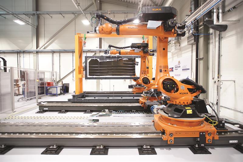
The VIEWS programme
CUE and the AFRC, in collaboration with Spirit AeroSystems, Prestwick, secured £1.5 million funding through the VIEWS programme (Validation and Integration of Manufacturing Enablers for Future Wing Structures) to commission new robotic inspection cell at the AFRC . Concluded this year, this was part of the 13-partner £30 million VIEWS programme that was part-funded through the UK Aerospace Technology Institute (ATI) and is aimed at innovative aircraft wing design, manufacture and assembly technologies (https://is.gd/peguno). A three-robot flexible inspection cell was commissioned at the AFRC to take fundamental research conducted in University of Strathclyde’s Department of Electronic & Electrical Engineering to higher technology readiness levels (4 to 6), suitable for future industrial exploitation.(below)