Vericut simulates NC code in a modelled environment, identifying in-process collisions, for example. The software already boasts Optipath, a feedrate optimisation software module that slashes rough machining time, but because it doesn’t ‘know’ anything about the material, it is still possible to break a tool: Force now resolves that issue, offering finite element analysis-based feedrate optimisation.
CGTech (https://is.gd/qafome) acquired the technology underpinning Force from United Technologies Research Centre (United Technologies Corporations’ [UTC] innovation operation), announcing that in August 2014. At that time, UTC was claiming productivity improvements of up to 50% in its own machining operations via what it calls PromptFM. CGTech’s Force was rolled out first in the USA some two years.
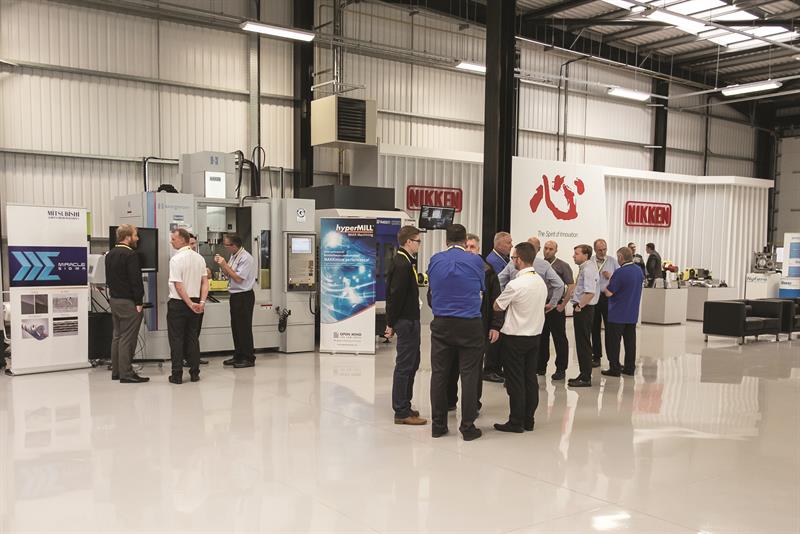
An event was held in July at Nikken Kosakusho Europe's unit on the Advanced Manufacturing Park
At an event held last month at Nikken Kosakusho Europe’s (https://is.gd/sexuco) location on the Advanced Manufacturing Park, which straddles Sheffield and Rotherham districts, a turbine blade form was the subject of a Force demonstration (at other events, the workpiece was different). A before- and after-optimisation run was made on a Bridgeport VMC using Nikken-supplied tooling, with the NC program itself generated by Open Mind Technologies’ hyperMILL MAXX Machining (https://is.gd/hajegi), a CAM system that itself generates optimised NC code. To cut to the chase, on the demonstrated part, roughing time was reduced by 47% (see box, p8, for details). But of key importance is that this optimised program delivers a reliable process, a consideration that is all the more important when machining challenging and expensive materials.
Processing such materials is going to become a preoccupation of far more, as CGTech sales engineer Scott Ravenscroft highlighted by pointing to future aircraft production volumes: 2010’s 972 became 1,397 in 2015, is projected to be 1,511 in 2020, 1,714 in 2025 and 2,206 in 2035, according to Deloitte 2016-2035 forecast figures (https://is.gd/penuno). These future aircraft will make greater use of titanium. That mix of factors is precisely what kicked off UTC’s investigations some seven years ago, he added, with the company building PrompFM that used Vericut Optipath output. CGTech has integrated PrompFM within Vericut as Force, so it is now a commercially developed and maintained piece of software.
OUTGROWING CAPACITY WORRY
A further worry expressed by UTC, Ravenscroft says, is the actual availability of the necessary industrial capacity to support such a doubling of volumes from 2010 to 2035, plus further increases beyond that. And in addition to the driver of increasing volumes of titanium parts can be added the cost-down initiatives of large companies such as UTC, which operates its ‘Supplier Gold’ programme and is asking its suppliers to use Force, while Lockheed Martin and its industry partners Northrop Grumman and BAE Systems operate the F-35-related ‘Blueprint for Affordability’ programme. Suppliers will be asked to produce more, at highest quality, while additionally driving down cost. CGTech’s Force is one answer to being able to meet the three challenges.
Okay, so how does Force do what it does? It is able, based on a specified material (which CGTech has characterised), to analyse cutting force, maximum chip thickness and spindle power for the as-programmed (post-processed) feed rates. The feedrate is then recalculated, based on use-specified data that takes in: maximum cutting force to be applied, maximum chip thickness and maximum spindle power. “The toolpath trajectory is not altered,” Ravenscroft underlines, and he went onto explain more about how Force works. “Force is looking at the cutting edge of the tool; cutter contact with the material. This is quite easy to imagine in a 3-axis world, but in 5-axis cutting tool contact is continuously changing and that is quite difficult to calculate. But Force looks at the tool contact point all the time, calculating a series of force vectors; there could be thousands of these along the tool.”
In analysing NC code as programmed, the result is a graph that plots force against time, with a typical output showing spikes in various axes. Force then optimises the feedrate to smooth out the spikes, taking the user-specified force as the maximum allowable figure. Capping force means that tool breakage issues are mitigated.
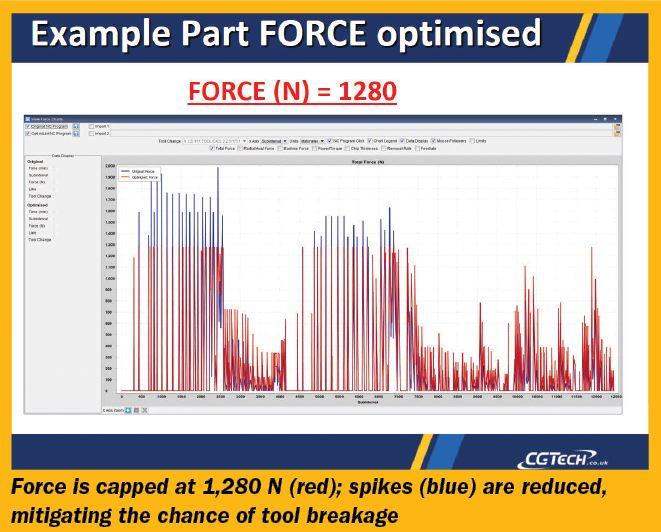
Cutting force is optimised; spikes are reduced
Also plotted is maximum chip thickness against time, and again the CAM-generated paths show variation. Limiting chip thickness below a specified maximum figure is achieved by Force altering feedrates. A chip thickness that is too thin can lead to premature cratering, thermal cracking or flank wear, while chips that are too thick indicate high cutting forces that can cause an insert to fail.
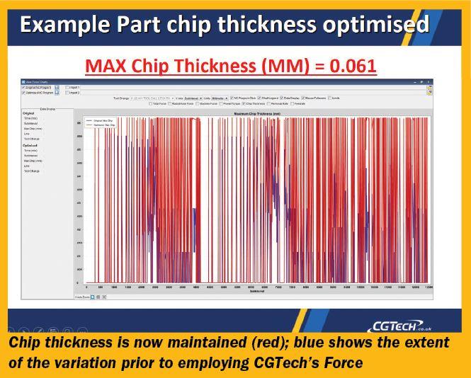
Chip thickness optimisation
Without the benefit of Force, NC programmers opt for safe, constant feedrates, and the CAM system applies these. However, what you think you have programmed is not what CAM systems necessarily deliver. “Even though you have programmed a chip thickness, your CAM systems are not achieving the chip thicknesses that you think you are,” Ravenscroft states. Adds CGTech sales engineer Rob Lightfoot: “The CAM system is calculating chip thickness internally, but it is not getting it from the in-process model, because there is no internal model. It calculates it geometrically.”
This is not a specific criticism of the CAM system employed for this demonstration, because a speaker from the floor that had undertaken an analysis of six or seven rough milling cycles in three different CAM systems to machine the same part using the same feeds and speeds said that all output code showed chip thickness variation, according to Optipath, even between rough milling cycles in the same package.
To support Force’s application, users must know and input four pieces of tool information: tool helix, radial rake, force limit and maximum chip thickness. The first two are known, but the latter two are, at the outset, unknown. Says Ravenscroft: “If you already have good cutting data that is running on a machine, you can establish those [last two] by analysis of the toolpath. But we are generally referring initially to the [tool supplier] recommended speeds and feeds, and running a [virtual] test cut.” That sees a simple line of code simulated within Vericut Force, which produces the two unknown parameters.
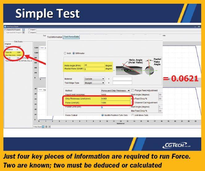
A simple test is required to generate data
With the four pieces of data now known, a program can be optimised by choosing one of three available options: maximum force and chip thickness (most likely); maximum power and chip thickness (if a company wants to prioritise spindle life, say); and chip thickness only (when force is not an issue). For the Nikken example, maximum force was capped at 1,280 N and chip thickness at 0.062 mm. Optimised feedrates are highlighted within the resulting NC program, so are clearly visible.
Available today is Force Milling, but support for turning and drilling are on their way, possibly in Vericut version 8.1. Material characterisations for use with Force are chargeable, but a module to support user-performed characterisation is scheduled. Compared to investing in another machine tool to boost capacity, purchasing Vericut and Force looks like an alternative worthy of consideration.
Box item
Milling process details
The machined part at the CGTech/Nikken Kosakusho Europe event was a titanium blade, cut from round Ti-6Al-4V bar. The machine tool was an Engineering Technology Group-supplied (https://is.gd/yovuyo) Hardinge Bridgeport XR1000 vertical machining centre (VMC) fitted with Nikken 5AX-350ZA 2-axis rotary table. The VMC also boasted 15,000 rpm spindle, 20 bar through-spindle coolant and Heidenhain TNC-530 control. Machining was carried out in three stages: 3-axis roughing; 3-axis semi-finishing with the part inclined at ±4º to allow access; then 5-axis finishing. Force reduced the roughing stage time by 47%, but this high figure is due to a large reduction in air-cutting time, Machinery was told; optimisation generally falls within the region 10-50%.
Tools used were, for roughing and semi-finishing, a six-flute Mitsubishi 20 mm diameter solid carbide Coolstar end-mill with 3 mm corner radius held in a Multi-Lock NBT20-C20-90G holder and run at a surface speed of 110 m/min, a programmed feed rate of 1,400 mm/min and programmed at 0.08 mm/tooth, although hyperMILL MAXX Machining (based on VoluMill technology – www.volumill.com) will have optimised cutter engagement during roughing. A 10% step over and 22.5 mm step down were applied for roughing, with ‘3D arbitrary stock roughing’ the hyperMILL strategy employed. For optimisation, Force was capped at 1,280 N and chip thickness at 0.062 mm; maximum feedrate became 4,500 mm/min.
Finishing was undertaken with a Mitsubishi 8 mm diameter coated solid carbide 4º tapered ballnose cutter at 110 m/min surface speed, 0.08 mm/tooth feed, taking off 0.75 mm. The strategy was a scanning one and probably not the approach likely to have been chosen in reality, Machinery was told.
First published in Machinery, August 2017


