
Provided that someone has written a measurement program for a part, the process of checking that components are within tolerance can be fast and almost brainless, involving only placing them on a machine’s stage (in any position or orientation), pressing a button on the equipment or on the computer and then waiting for results to come up on the screen.
Automatically adjusting focus and illumination (in most cases using an LED array laid out in a ring, but sometimes lights that shine up from underneath the stage), the units’ integrated digital cameras take a picture of the part. Then they fire up software to automatically fit geometry, such as circles and lines, around automatically-identified features. This process generates a digital model of the part that can then be compared (again, automatically) to a reference model extracted from a CAD file, producing a pass/fail indication for each feature. Additional reporting or analysis software is offered by some vendors (Keyence, OGP).
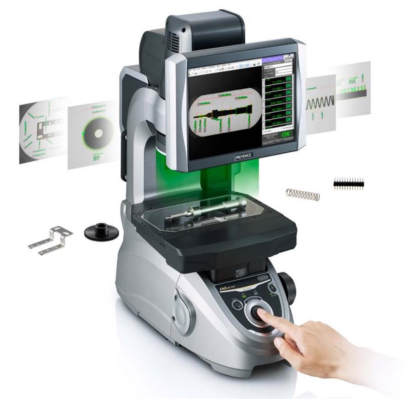
Three of the four systems covered here are geared to small parts, with a measurement area of around a 100 by 100 mm square, for which accuracy or repeatability is claimed to be in the 5-10 micron range, mostly. Special so-called ‘telecentric’ optics are used in most of these machines to make sure that visual perspective does not distort parts with deep features.
A touch-probe for depth measurement is an option from Keyence, InspecVision and OGP. The latter goes beyond this to offer two other ranges of dedicated 3D automatic or semi-automatic measurement systems in the form of the Sprint and StarLite models, all manufactured by QVI.
Naturally, writing the measurement program takes longer than the measurement itself, though each vendor seems to have a different way of making quick work of it. Some vendors (Keyence, OGP) offer desktop PC software to write them offline. Some offer software (OGP, Zeiss) that provides extra assistance in writing programs.
Detailed capabilities of the four brands selected for this article follow.
● The QVI RAM Snap benchtop digital measuring machine from OGP (01283 585933) comes in three models; an entry-level Snap 100 unit; a model with 150 by 75 mm manually-operated stage (Snap 200); and a unit with 350 by 350 mm motorised stage. Its bundled Measure-X software includes a comparator mode that overlays the digital model and tolerance over the video image for visually comparing actual and nominal dimensions.
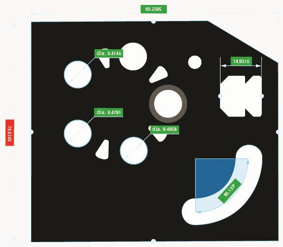
The Zeiss O-Select user interface presents measurements next to the relevant features
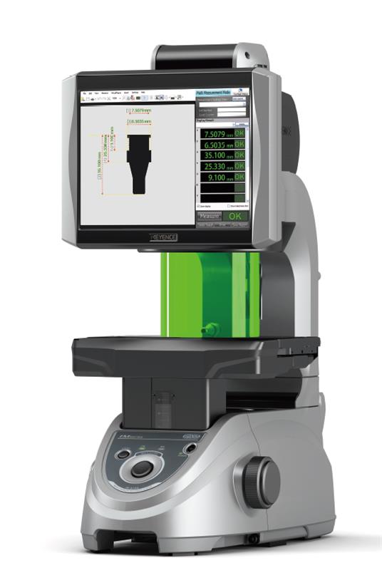
● Zeiss’s O-Select digital projector part measuring system (01788 821770) features a touchscreen display. The system offers what the German manufacturer calls “a real innovation”: rather than going through menus, most measurements are selected using the image of the part, andmeasurements are displayed next to the feature, right on the drawing.
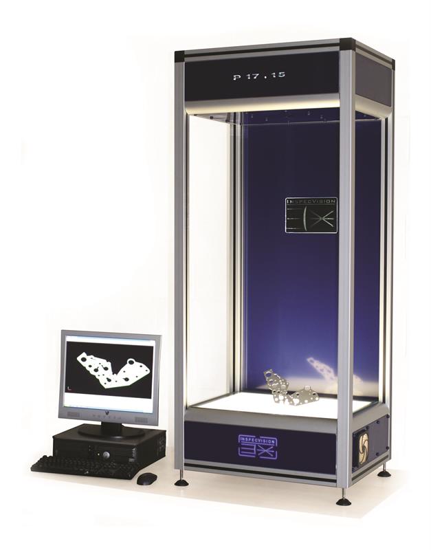
● InspecVision Planar (02890 844012) has a reasonable claim to be the fastest in making measurements: 40 million can be made in 0.1 sec, although, as anyone who has ever used a shutter burst mode on a digital camera knows, images taken in quick succession still require real time to process. That’s of the order of 20 sec, according to the company, or 4 sec as an option. On the other hand, InspecVision saves time by automatically extracting product and manufacturing information (PMI) from CAD files for writing measuring programs. Also, as they are designed for full-size sheet metal parts, InspecVision’s 11 Planar models are much larger than the others: the smallest offers a 500 by 333 mm platen, the biggest 2,355 by 1,570 mm.
This article was originally published in the January 2017 issue of Machinery magazine.


