
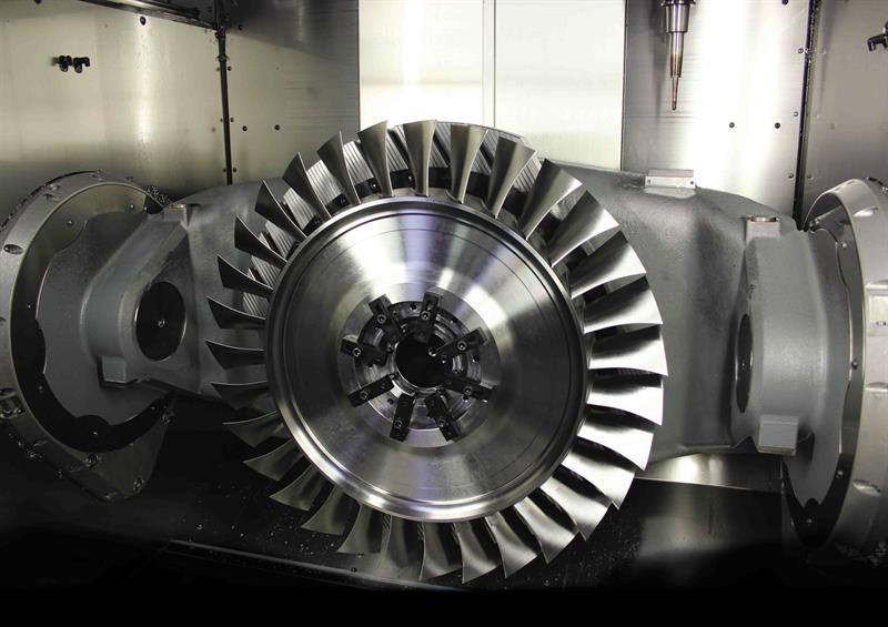
The word ‘blisk’ is a portmanteau of ‘bladed disk’: a solid ring of aerofoil blades ranged around a central hub; these generate rotational motion from the force of air blowing through an aeroengine.
Blisks have so far been found mainly on military aeroengines, for example in compressor stages of the EJ 200 Eurofighter engines and the vertical LiftFan for the F-35 Joint Strike Fighter. But there are signs that the blisk is moving into commercial aerospace. The Rolls Royce Trent XWB engine (intended for Airbus A350 commercial aircraft family), for example, is saving 15% in weight by employing blisks in some compressor stages: a savings that soon repays back the investment in reduced fuel consumption over the course of the engine’s working life.
As they are machined from solid, blisks offer better structural integrity than discs, which consist of a single slotted hub into which are pressed separately made aerofoil blades. (In fact the Eurofighter and F-35 blisks are actually a hybrid technology in which blades are bonded to hubs using a special linear friction welding process).
Now the custom development operation of CADCAM developer Delcam, Delcam Professional Services, is working to drive down the cost of blisks by developing a new process by which to make them.
Nowadays, perhaps a third of the work carried out by Delcam Professional Services is customised work solving individual customers’ problems, says Mark Forth, Delcam advanced manufacturing product manager, taking in not only the cutting strategy but also the machine tool, fixturing, cutting tools, probing and inspection. From Delcam’s Birmingham headquarters, Professional Services offers CADCAM expertise and has access to machine tools in Delcam’s workshop that are used to verify and optimise the company’s CAM software.
The Professional Services operation has seen growing interest from commercial aerospace firms to alleviate R&D pressure at a time of accelerating production volumes, says marketing manager Peter Dickin.
About a year ago, Delcam Professional Services started a project to develop a new way to manufacture blisks. Making blisk aerofoils, which usually consist of a series of full-depth roughing, semi-finishing and finishing passes, presents a few machining challenges: aerofoils are so thin and long that they move; they wobble a lot, and that movement causes problems during cutting. In particular, the load on the tool keeps changing, explains Forth. “You get a constant push me–pull me effect, where the tool is being pushed away or pulled into the material. If you look down the blades, you can see the witness marks where the tool has gone from having only a slight amount of material to a lot of material at tip and it is pulling it in; then you have to leave a little bit of thickness on and perform a polishing process to finish off the blade.”
Removing witness marks requires another surface finishing step in the manufacturing process, with consequent delay and risk of error; if the marks are deep enough, they can even fail the part, according to Delcam.
Of course, the machine tool industry has devised many ways to reduce witness marks by managing cutting conditions such as speeds, feeds and directional changes. For example, within the Dynamic Efficiency technology available on its TNC 640 control, Heidenhain’s Adaptive Feed Control system (01444 247711) works with other software to adjust feed rates, depending on the forces acting on the spindle.
Delcam’s solution approaches the problem from another direction, Forth states: “Because we have more flexibility with the editing options in PowerMILL, we can change the toolpath, rather than speeding up or slowing down the feed rate, which can have other dynamic effects that we’re not privy to or fully understand.
“But we are all trying to get to this position where the virtual world in the PowerMILL software meets the real world of the machine tool. You can’t just have a toolpath that knows nothing about the tooling, the machine and its feeds and speeds and horsepower, because without these we can’t control other things that we are doing.”
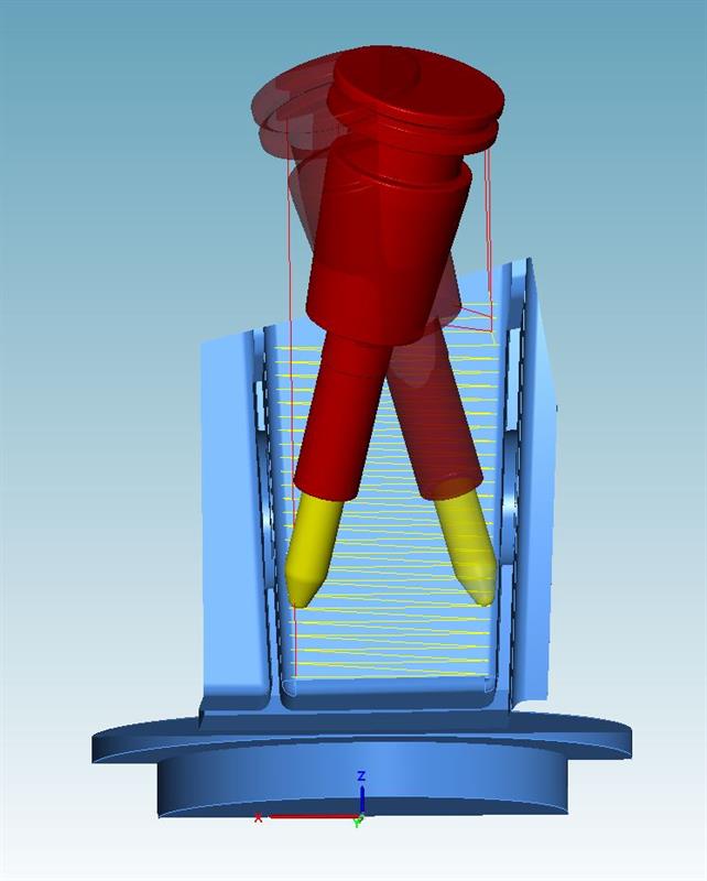
Delcam’s new toolpath combination puts a new spin on aerofoil machining. First, a slotting operation cuts out each aerofoil profile, disrupting the hoop stresses in the billet imparted from the forging process and forcing the blade to shift slightly. After that, each aerofoil is processed in multiple vertical sections from blade tip to root; lower sections are left in the roughed state to keep the blade stiff; each processing cycle of an aerofoil section includes both semi-finishing and finishing processes. A final pass with a ballnose cutter produces the aerofoil root.
Wilkinson explains: “There are some gross changes that will occur in the blade during roughing, so you want the blades to wriggle and die [after slotting]. They wriggle and die very quickly. Then you go through the semi-finishing and finishing stages. Our algorithms have built a structural support on these blades; we leave material on until the last moment. When final finishing takes place, the only distortions there are due to tensile stress distortion: the blade pushing away from the tool.”
The key to the process is a special type of barrel-profile tool made by Technicut (0114 256 0036); these have a large radius taper down the tool body. Although less common than flat end-mills and round ballnose cutters, these so-called barrel tools have been used before for semi-finishing and finishing of blades and other aerospace parts; but this project marks the first time they have been used with a ripper geometry for removing large amounts of material, says Delcam.
Explains Delcam Professional Services senior consultant Ian Caldicott: “The barrel concept allows you to have a larger stepdown, because the radius of the tool is significantly larger than the radius you’d have on a ballnose end-mill. So you can generate the same level of cusp with a larger stepdown – three to four times as much as a ballnose.”
The greater the stepdown, the fewer passes are needed, so the faster the process and the smoother the surface finish.
Unusually, it was Delcam that designed the tooling, rather than designing a toolpath to fit new tooling. Doing so required a close relationship and good communication with the tooling supplier; Delcam has worked with Technicut for more than 10 years. In particular, Paul Wilkinson adds, Delcam needed to have faith in Technicut’s toolgrinding capability to produce the radiuses and features that it required to support its cutting strategy.
“They [Technicut] knew we were good at machining blisks, and they had been approached by end users about blisks,” Caldicott recalls. “The problem they have is that they need their cutting tools to be driven in a specific way, but every different subcontractor has a different CAM system and programmer. They didn’t have control over how the parts are programmed.”
For just this reason, Delcam has had success partnering with not only Technicut but also tooling manufacturers SGS Tool Europe, Sandvik Coromant and Seco Tools to resolve particular manufacturing problems.
“The productivity you can get out of new cutting tool designs is potentially significantly greater than that achieved four to five years ago, but you need people who understand the technology,” says Delcam’s Dickin. “Because high speed cutting tools are often quite brittle, you can’t plough them into the material. You have to have sophisticated cutting strategies to protect the cutter.”
And with its available facilities, Delcam is able to develop them.
Process statistics
Tools and workholding
Titan X-treme ripper end-mill
Barrel ripper
Ballnose ripper
Barrel finisher
Taper ballnose
Nikken X-treme chuck
Sample case study
800 mm diameter blisk in Ti-64
31 blades: 120 mm high, 84 mm chord length
35 hour cycle time
Milling cost: £1,217
Total tools used: 18
Machine tool: Hermle 5-axis C 50 UMT machining centre with turning capability, offering travels of 1,000 by 1,100 by 750 mm in X, Y and Z, with a 12,000 rpm HSK A 100 spindle, high pressure coolant (up to 26 l/min) and coolant chiller. Rapids are up to 60 m/min travel (X and Y; Z is 55 m/min). Control: Siemens 840D
Blisks and adaptive machining
One advantage of aeroengine discs over blisks is that individual damaged blades can be swapped out. But that does not mean blisks are unrepairable. Delcam has devised a new process for blade repair using additive manufacturing to deposit material and then machine it for blade repair, using the Hybrid Manufacturing Technologies’ Ambit AM head (see also Machinery June 2015, p. 14-16). Whilst a traditional subtractive manufacturing process would touch every bit of metal in a part, these repair operations aim to preserve some parent material, with new solid material welded to the blades and then machined to produce a final blade to a condition that might have to take account of work hardening and distortion seen in a used blade. Delcam Professional Services general manager Paul Wilkinson explains: “Adaptive machining is, dynamically on the fly, morphing a nominal design of a blade from a CAD model into what exists in the machine.” He reveals that Delcam already has contracts for this service.
Delcam’s project to cut blisks was originally inspired by another project to develop a mechanised polishing system. Paul Wilkinson, general manager, Delcam Professional Services, says: “The alternative is to use our hands: these are great to some degree, but the world’s changing, and quickly. That activity of removing material to blend surfaces is a very defined skill. I’ve seen it in so many places; very skilled people doing a horrible job.”
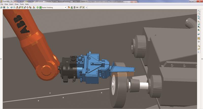
The system, developed by Delcam Professional Services in association with Finland-based JOT Automation, was shown at EMO in Milan last month on an ABB robot driven by a combination of Delcam software, including PowerMILL Robot and PowerINSPECT.
First, the robot completes an initial pattern of measurements on the blade surface by lifting the blade towards a fixed probe. These measurements are passed to PowerINSPECT to determine the amount of stock material remaining on the blade. The information is used by PowerMILL Robot to produce the polishing paths. During the operation, the blade is moved against a disk within the cell. Once the routine is complete, a further series of probing measurements is taken to check that the required amount of material has been removed and that the blade is within the specified tolerances. If it isn’t, further polishing can be undertaken until the blade conforms to the required dimensions. A video of the process can be seen at http://bit.ly/1RVAk1b.
Box item
Over a barrel
A new barrel tool cutting strategy features heavily in recent versions of CAM software HyperMill from supplier Open Mind Technologies (01869 290003). The company has collaborated with tooling manufacturer Quickgrind (01684 294090) to develop the Maxx Machining Strategy that supports geometry and collision checking of conical barrel cutters, tangential barrel cutters, lens tools and barrel tools. All increase tool step-over rate to improve productivity.
Last month, it showed off the system at DMG Mori in Coventry, after launching it at Yamazaki Mazak in Worcester in May.
Open Mind claims that the roughing module can reduce cycle times “by over 90%, regardless of your existing CAM software and strategies”. It adds: “This ‘next step’ in machining strategies is so far ahead of the industry that only a limited number of cutting tool vendors are supporting the production of such tools.”
This article was originally published in the November 2015 aerospace supplement of Machinery magazine.


